DXF
Inventor Drawing
Conversion method: Inventor translator addin
Supported files: idw, dwg
Important
Warning
The used translator-addin, will not read any settings from the configured .ini -file other than Export_Acad_IniFile.
Instead it will read all the settings from the specified file. In order for it to be able to read the settings from the same file, you must set the Export_Acad_IniFile setting to the path of the .ini-file itself.
An example can be seen below.
Note
When exporting multisheet IDW or DWG files, Inventor creates foreach Sheet a own dxf file.
By setting the flag USE TRANSMITTAL to Yes, the result will be a zip file with same name as the destination dxf file instead.
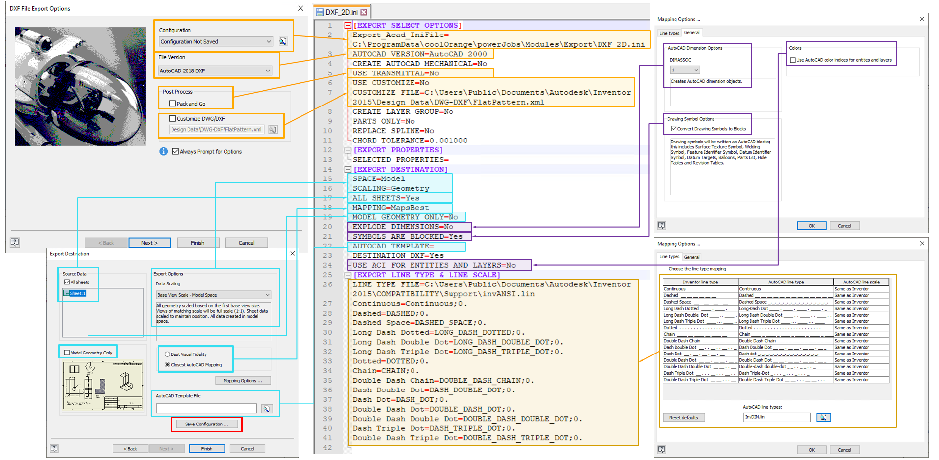
How the 2D DXF Settings relate to the Inventor User Interface
Warning
If you created an .ini-file via Inventor you must ensure that it contains a setting “Export_Acad_IniFile” which value is set to the path of the .ini-file itself.
Without this you won’t be able to use it in -Options.
Sample configuration (Drawing)
[EXPORT SELECT OPTIONS]
Export_Acad_IniFile=C:\ProgramData\coolOrange\powerJobs\Modules\Export\DXF_2D.ini
AUTOCAD VERSION=AutoCAD 2000
CREATE AUTOCAD MECHANICAL=No
USE TRANSMITTAL=No
USE CUSTOMIZE=No
CUSTOMIZE FILE=C:\Users\Public\Documents\Autodesk\Inventor 2015\Design Data\DWG-DXF\FlatPattern.xml
CREATE LAYER GROUP=No
PARTS ONLY=No
REPLACE SPLINE=No
CHORD TOLERANCE=0.001000
[EXPORT PROPERTIES]
SELECTED PROPERTIES=
[EXPORT DESTINATION]
SPACE=Model
SCALING=Geometry
ALL SHEETS=Yes
MAPPING=MapsBest
MODEL GEOMETRY ONLY=No
EXPLODE DIMENSIONS=No
SYMBOLS ARE BLOCKED=Yes
AUTOCAD TEMPLATE=
DESTINATION DXF=Yes
USE ACI FOR ENTITIES AND LAYERS=No
[EXPORT LINE TYPE & LINE SCALE]
LINE TYPE FILE=C:\Users\Public\Documents\Autodesk\Inventor 2015\COMPATIBILITY\Support\invANSI.lin
Continuous=Continuous;0.
Dashed=DASHED;0.
Dashed Space=DASHED_SPACE;0.
Long Dash Dotted=LONG_DASH_DOTTED;0.
Long Dash Double Dot=LONG_DASH_DOUBLE_DOT;0.
Long Dash Triple Dot=LONG_DASH_TRIPLE_DOT;0.
Dotted=DOTTED;0.
Chain=CHAIN;0.
Double Dash Chain=DOUBLE_DASH_CHAIN;0.
Dash Double Dot=DASH_DOUBLE_DOT;0.
Dash Dot=DASH_DOT;0.
Double Dash Dot=DOUBLE_DASH_DOT;0.
Double Dash Double Dot=DOUBLE_DASH_DOUBLE_DOT;0.
Dash Triple Dot=DASH_TRIPLE_DOT;0.
Double Dash Triple Dot=DOUBLE_DASH_TRIPLE_DOT;0.
Warning
The .ini-file below contains paths which reference “Inventor 2015”. If you are using another version than Inventor 2015 you have to update them.
Inventor Sheet Metal
Conversion method: DataIO
Supported files: sheetmetal ipt
Important
The full list of arguments for the DataIO addin can be found here.
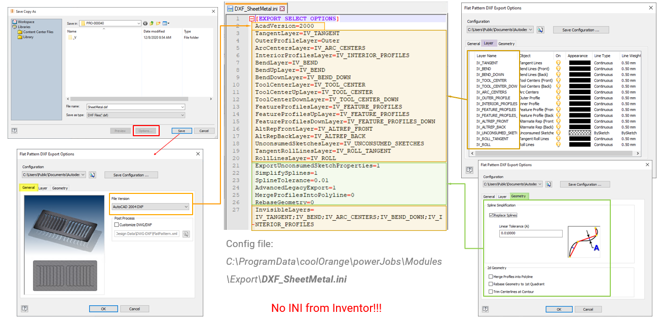
How the Sheetmetal Settings relate to the Inventor User Interface
Warning
It is NOT possible to use .ini-files created by Inventor for this export!
The sheetmetal export internally uses DataIO, which is not compatible to the configuration files created in the Inventor user interface (see the Autodesk forum for more details).
Sample configuration (Sheet Metal)
[EXPORT SELECT OPTIONS]
AcadVersion=2000
TangentLayer=IV_TANGENT
OuterProfileLayer=Outer
ArcCentersLayer=IV_ARC_CENTERS
InteriorProfilesLayer=IV_INTERIOR_PROFILES
BendLayer=IV_BEND
BendUpLayer=IV_BEND
BendDownLayer=IV_BEND_DOWN
ToolCenterLayer=IV_TOOL_CENTER
ToolCenterUpLayer=IV_TOOL_CENTER
ToolCenterDownLayer=IV_TOOL_CENTER_DOWN
FeatureProfilesLayer=IV_FEATURE_PROFILES
FeatureProfilesUpLayer=IV_FEATURE_PROFILES
FeatureProfilesDownLayer=IV_FEATURE_PROFILES_DOWN
AltRepFrontLayer=IV_ALTREP_FRONT
AltRepBackLayer=IV_ALTREP_BACK
UnconsumedSketchesLayer=IV_UNCONSUMED_SKETCHES
TangentRollLinesLayer=IV_ROLL_TANGENT
RollLinesLayer=IV_ROLL
ExportUnconsumedSketchProperties=1
SimplifySplines=1
SplineTolerance=0.01
AdvancedLegacyExport=1
MergeProfilesIntoPolyline=0
RebaseGeometry=0
InvisibleLayers=IV_TANGENT;IV_BEND;IV_ARC_CENTERS;IV_BEND_DOWN;IV_INTERIOR_PROFILES
Spline
A spline is a curve that passes through a set of points which influence the shape of the curve.
To disable the replacement of splines with linear segments, the flag SimplifySplines must be turned off.
This setting is activated by default and the corresponding chord tolerance can be ajusted with the option SplineTolerance (see (A) in the screenshot above).
When this double value is set to 0, the spline passes directly through the fit points. With larger tolerance values, the spline passes near the fit points.